The Piper Cherokee constant chord “Hershey Bar” and tapered wings exhibit significantly different landing behaviors. In particular, the newer tapered Cherokee wings are known -two examples are at https://www.flyingmag.com/rectangular-wings/ and at pilotfriend.com– to give substantially longer landing float than the constant chord wings -all other things being equal. In this note, I will discuss 4 reasons for this behavior and allow you insight into how design choices affect performance.
A Starting Point: Geometry
For the purposes of this engineering note, we will focus on the 180 hp versions: the PA-28 180 (constant), PA-28 180 Extended and PA-28 181 (tapered). The geometries taken from three POHs are in Figure 1:
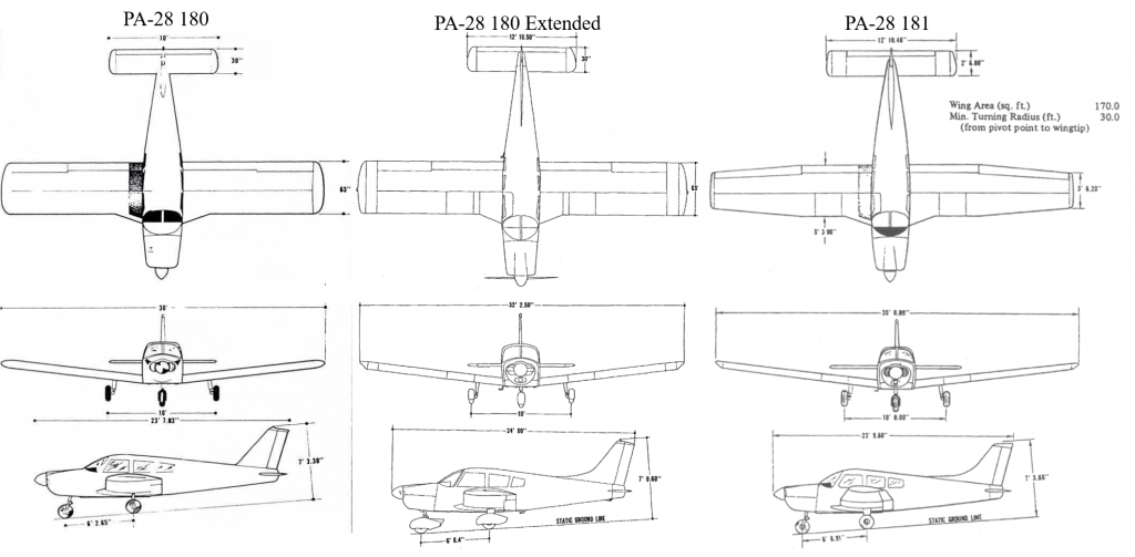
The aircraft are essentially identical except for the wing planform, so for more insight, zoom into the wing shapes with Figure 2.
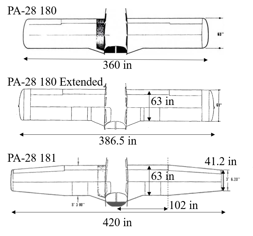
The tapered wing has a longer wingspan (35 ft vs 32.25 ft vs 30 ft) but the same root chord of 63 in. In fact, the PA-28 180 Extended and 181 have 170 ft2 wing areas whereas the 180 has 160 ft2. The constant chord wings have no washout. The tapered wing has 3 degrees of washout at the tips.
Reason #1: Wing Area
The tapered and extended constant chord wing have about 6% more area than the shorter 180 wing. All things equal, the tapered wing can operate at a 6% lower lift coefficient compared to the constant chord wing. Since induced drag is proportional to k CL2 , we might expect the tapered wing’s CL2 to be about 12% lower than the constant chord wing.
Reason #2: Aspect Ratio
Increasing aspect ratio, AR, tends to decrease induced drag for a given lift coefficient – all other things equal. The tapered wing has an aspect ratio of b2/S = 4202/170 = 7.2. The extended constant chord wing has an aspect ratio of 6.5. The shorter constant chord wing has an aspect ratio of 5.7. From Prandtl lifting line theory, we expect the induced drag to be about 10% lower for the higher aspect ratio wing (i.e. the ratio of AR), since induced drag is proportional to k CL2 where k is approximately 1/(pi AR).
However, this does NOT tell all of the story. The tapered wing is operating closer to the optimal elliptical lift distribution such that the induced drag is lower still. Using my Prandtl lifting line software, the wings’ geometries and the airfoil properties, I computed the following lift distributions (blue curves) across an AOA range from -5 to 15 degrees in Figure 3.
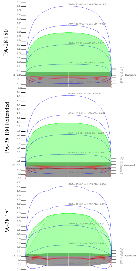
Notice that the constant chord wing has significantly more downwash (red curves) at the tips. This lift distribution is not elliptical as the downwash is not constant. In contrast, the tapered wing has less downwash at the tips and more closely approaches an elliptical lift distribution, especially at cruise flight conditions.
But what does this mean? Plotting the induced drag indicates that the extended wing has an induced drag 17% lower than the constant chord wing. The tapered wing has an induced drag 32% lower than the constant chord wing.
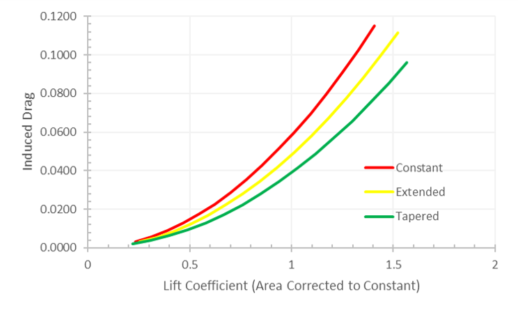
Increasing span and carefully tapering a wing significantly decreases overall induced drag.
Reason #3: Ground Effect
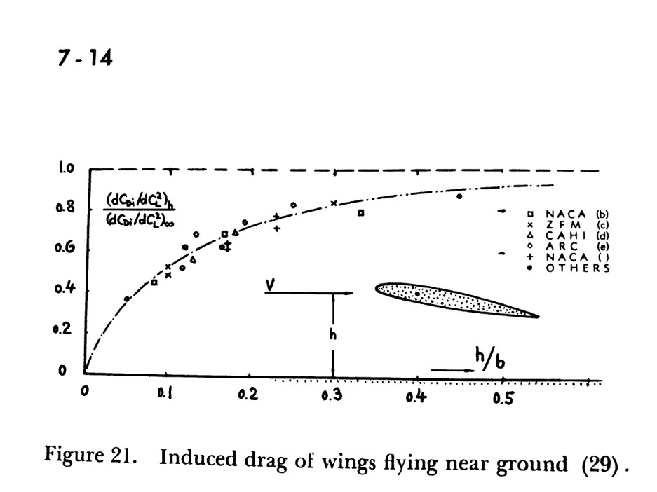
Ground effect strongly changes the magnitude of induced drag. Estimating the mean wing height gives a height/wingspan ratio of 0.086 for the constant wing, 0.084 for the extended wing and 0.0825 for the tapered wing. Using Hoerner’s estimate of the reduction of induced drag below, the short wing estimate is 48% of the free-air induced drag, the extended wing 47% and the tapered wing 46%.
Although the change in magnitude is substantial, the ratio delta between the wings is relatively minor. Surprisingly, the tapered wing’s dihedral coupled with a longer wingspan would tend to mitigate differences between the wings.
Reason #4: Airfoil drag bucket
The PA-28 series uses the NACA 65(2)-415 airfoil, sometimes categorized as a laminar flow airfoil, although this is not precisely what happens in operation. A better characterization is that the airfoil naturally has a favorable pressure gradient across a substantial portion of the upper surface. The favorable pressure gradient (i.e. increasing speed and decreasing pressure) tends to keep the airfoil’s drag down and tends to form a “drag bucket”. The airfoil and pressure profile at CL = 0.2 using xfoil is in Figure 6.

Increasing AOA to CL=0.7 in Figure 7 shows the airfoil leaving the drag bucket region. The favorable pressure gradient on the upper surface is gone.

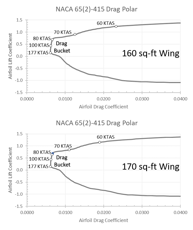
A typical airfoil shows an increase in profile drag with lift coefficient. This term has the same behavior as induced drag. Plotting the drag coefficient versus lift coefficient for a known wing area allows adding a rough estimate of the airspeed to the drag polar (Figure 8). These drag polar points for the 160 and 170 square foot wings are below. Notice that the 170 sq-ft wing has less airfoil drag for a given airspeed. This is particularly true at the lower airspeeds, such that at 60 knots the airfoil drag is about 30% lower with the 170 square foot PA-28 181. The critical airspeed for airfoil profile drag is about 80 knots.
Overall, Piper’s choice of the NACA 65(2)-415 is an excellent decision across structural and aerodynamic realms. The airfoil has a maximum thickness of 15% at 40% chord, which provides excellent depth for a high performance and light weight spar and excellent chordwise depth for fuel. The airfoil tends to provide consistent and smooth stall characteristics. The airfoil has a nice drag bucket in the aircraft’s effective operating region. The leading and trailing edges have a manageable radius and thickness. Overall, this was an excellent choice.
Conclusions
Gathering these results, the extended wing PA-28 has about 75% of the drag of the short wing PA-28 at touchdown. The tapered wing has about 60% of the drag of the short wing PA-28 at touchdown. Additionally, the overall induced drag for all variants of the Cherokee is reduced more than 50% when in groundeffect. Additionally, the effective geometric angle of attack for stall reduces in ground effect (c.f. Hoerner’s Fluid Dynamic Lift). These all contribute to a substantial difference during the final, flare and landing. Excess approach energy, especially when above 80 KTAS, will only slowly bleed away in ground effect.
Pilot reports that the tapered wing Piper Cherokee PA-28 floats more than the constant chord wings are completely substantiated with the engineering and physics analysis. Transitioning from a constant chord to a tapered wing Piper Cherokee has the potential to be particularly sensitive to the approach and flare speeds.
Comments
Comments? Contact me at oneill@aerofluids.com
Notice that this analysis is not meant to explore pilot techniques; you must refer to a qualified CFI for aircraft instruction. Fly safe.
There are limitations to this analysis. Some of these are:
- No dynamics
- No fuselage
- No flaps
- No trim or S&C
- Averaged CL for airfoil analysis
- Simple Prandtl Lifting Line model with Zero-Lift approximation