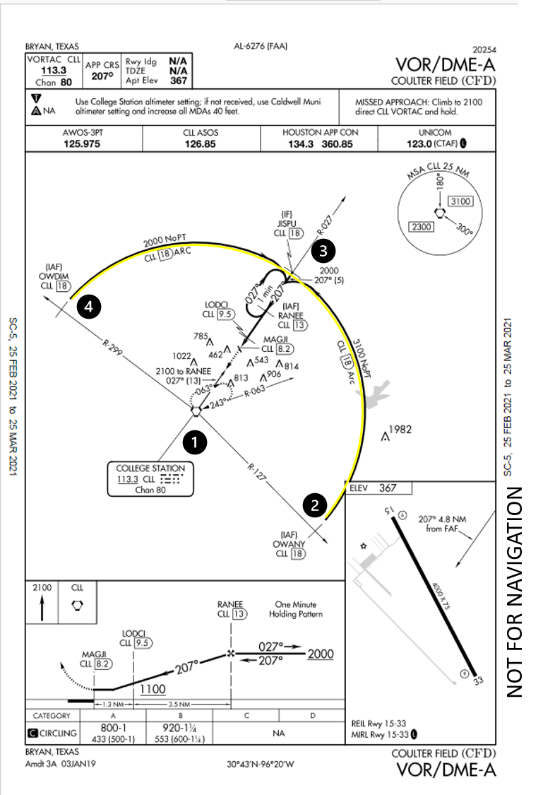
In this note, you will discover a trigonometric identity to assist maintaining a DME arc. The DME arc is a common maneuver for instrument approach procedures consisting of flying a specified distance from a DME site. The VOR/DME-A approach (Figure 1) uses an 18 nm arc from the CLL Vortac at (1) to provide two arcs (highlighted in yellow) from IAFs at OWANY at (2) and OWDIM at (4) towards JISPU at (3).
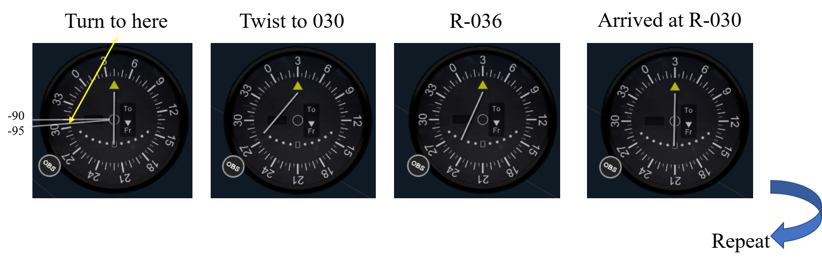
Using a Turn-Twist strategy, once on the arc, the heading to fly is tangent to the arc. This makes the no-wind control law: Turn to heading = Radial plus 90 deg when CW or Radial minus 90 deg when CCW. Unfortunately, this control strategy contains inherent divergence; in other words, the aircraft always tracks outside the desired arc (Figure 2, left). With a Turn 10/Twist 10 step, the cross track error is 1.5%. For example, a 20 nm arc with 10 degree radial steps, would give 0.3 nm error every step.
Is there a correction to exactly remain on the arc given a Turn-Twist step? Yes, and amazingly enough, the result is exact and a trigonometric identity. The right portion of Figure 2 derives a correction angle (gamma) such that the exact track is from point A to point B, both on the same arc. The result is that exactly half the Turn/Twist angle is applied inside the normal +-90 heading.

For example, using a Turn 10/Twist 10 in a counter clockwise direction at the R-040 would require the heading be 305 degrees; this heading will precisely keep you on the exact DME arc at the R-030 radial.
Warning: The normal flying caveats apply: 1) This is only meant for insight and is not meant as instruction or as a change to your specific flight operations manual, 2) wind will require varying correction angles, and 3) aviate, navigate, communicate.