
In this note, I will design an articulated 4 bar mount for a radar system using CATIA. The system needs to be designed and built rapidly for a VIP demonstration. Here’s the design:
First, the design requirements and needs:
- Precise pointing requirements from nadir (straight down) to horizontal.
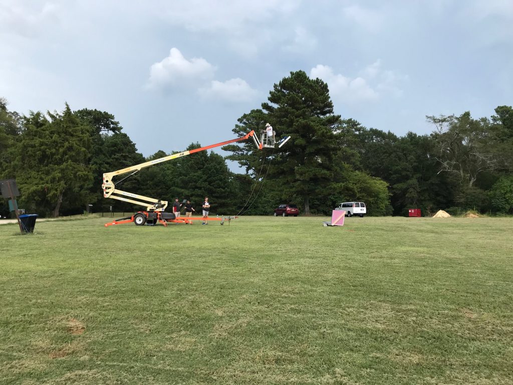
- Mount on a boom lift / cherry-picker bucket
- Separate two antennas of 30 pounds and 10 pounds by at least 2 meters with less than 1 deg of twist.
- Designed, sourced, and built within a tight schedule
The articulated arm as designed by CATIA met the design goals with a commonly available actuator. The use of a CAD model allowed for tuning of the geometry and resulting kinematics.
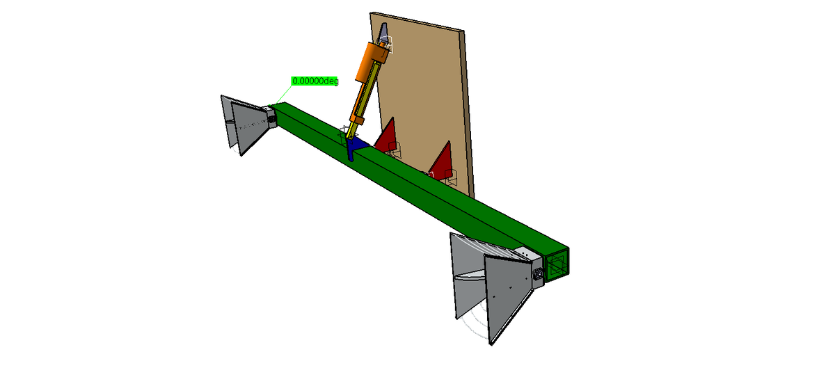
Using the gearing ratio between the actuator and the output angle, conservation of power, and the measured actuator dynamics, I was able to analyze, simulate, and tune the dynamic/transient dynamics of motion of the system. This analysis allowed for a truly coupled actuator/mechanism design and ensured that my design remained feasible across the entire operational envelope.
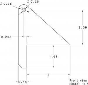
Design drawings were created to construct the actuation arm.
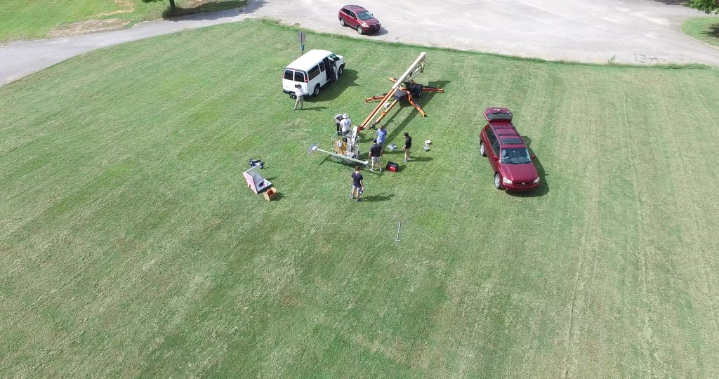
The as-constructed articulated arm met the design requirements and when mounted on a boom-lift was successfully was used for a data collection experiment.
This articulated arm mechanism’s development shows the power of CAD with CATIA for rapid support of R&D projects. I was pleased.