I receive many questions about the fuel systems of Piper PA-28 Cherokees, Arrows, and PA-28-235 Pathfinders. A common question is:
How can I modify my PA-28 to add tip tanks from the PA-28-235?
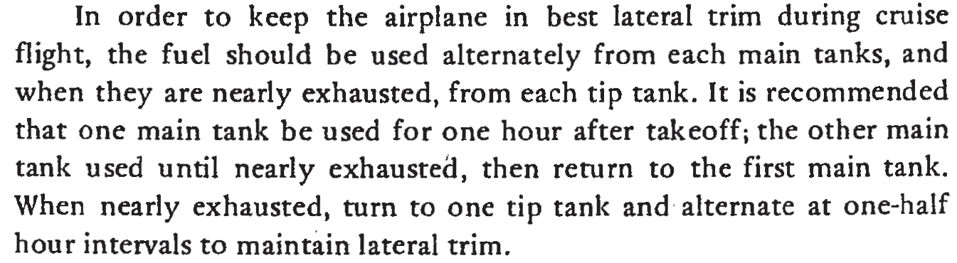
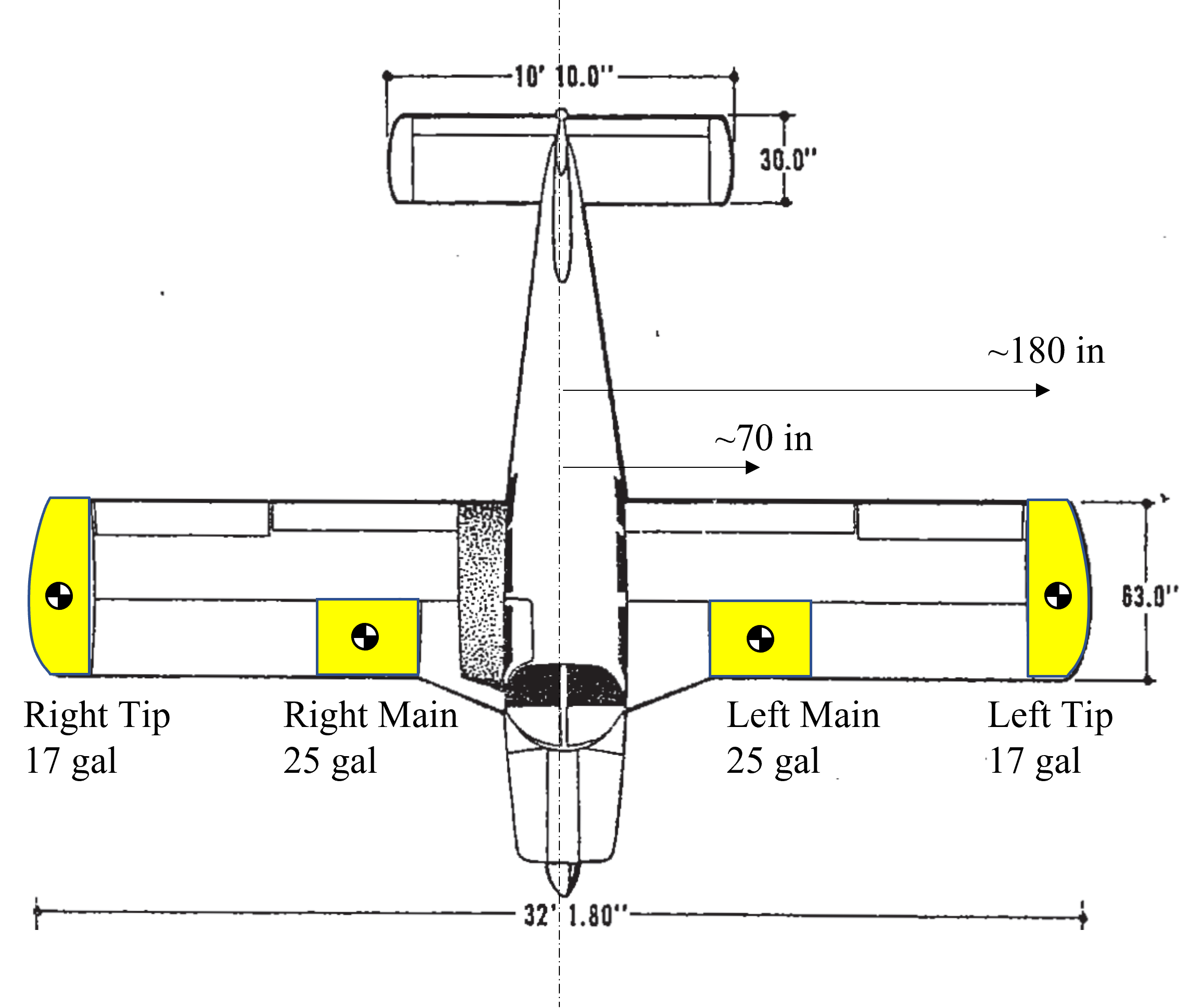
Thanks for the question. You have a good point, as the PA-28 Hershey bar wing chord is common across the PA-28R Arrow and PA-28 Cherokee variants prior to the tapered wing. Plus, the PA-28-235 and the Cherokee 6 have two 17 gallon tip tanks for a total of 84 gallons.
Yet, for all of the advantages of these tip tanks, I’ve never seen or heard of them being retrofitted into a non-235 Cherokee or Arrow. I suspect that there are three primary reasons.
1) This modification is a major change and will require substantial engineering and flight testing work. I’m not aware of any STCs available.
2) The plumbing and fuel management systems are substantially different between the tip and non-tip PA-28 variants. Plus, the tip tanks significantly increase the fuel management decision making. The tips have capital and maintenance costs too.
3) The aircraft endurance/range performance in the stock aircraft is equal to or exceeds the normal endurance performance of the pilot and passengers. Additionally, adding 34 gallons of fuel effectively removes 1+ passenger, as you are unlikely to increase the certified gross weight for climb and structural performance reasons.
Given these negatives, how would I approach the installation of more fuel?
1) Sell the Arrow and buy a Bonanza.
2) Selling the Arrow and buying a Lance won’t work, as the larger engine burns substantially more fuel. I burned 9 gph in an Arrow and 14 in a 235.
2) Add the PA-28-235 tip tanks but *don’t* copy the -235’s fuel system. Rather use a gravity or electrical pump into the existing fuel line, such that you one-way transfer fuel into the mostly empty main tanks. This has the potential to be an easier and safer certification path.
Now for the lawyer statements: 1) I am not advocating this process. Buy the Bonanza and be done with it. 2) I have not and will not indicate the legal, structural, or performance suitability of this process except under contract. 3) I am not presenting myself as a Designated Engineering Representative DER.
The answer really is no unless you have unlimited funds and time.