
Full memo: AEM495-2014-M02-revA
This post concerns a reverse engineered CAD model of the Cessna Citation 2. The objective of this memo is to provide a quick evaluation of the model with respect to the aerodynamics.
The model was supplied in a .STEP format by GrabCAD.com. It should be noted that the loft geometry presented is not an official Cessna geometry; the geometry was solely determined by reverse engineering. The as-supplied model required moderate loft-cleanup and surface trimming with CATIA. The cleaned model is illustrated in Figure 1. The forward hatch area was particularly difficult as the original model attempted to represent the hatch gaps with a tangential double fillet.
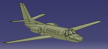
Figure 1: Citation CAD model (full aircraft)
A significant loft issue in the canopy area was spotted with zebra lighting (see Figure 2) at the intersection of the cylindrical fuselage and the complex canopy surface. From the zebra lighting, this region does not appear to be either tangentially or curvature constrained. This canopy loft issue will appear as a local accelerated flow region with detrimental downstream separation. A comparison with the actual Citation surface reveals that the current CAD model poorly represents reality.
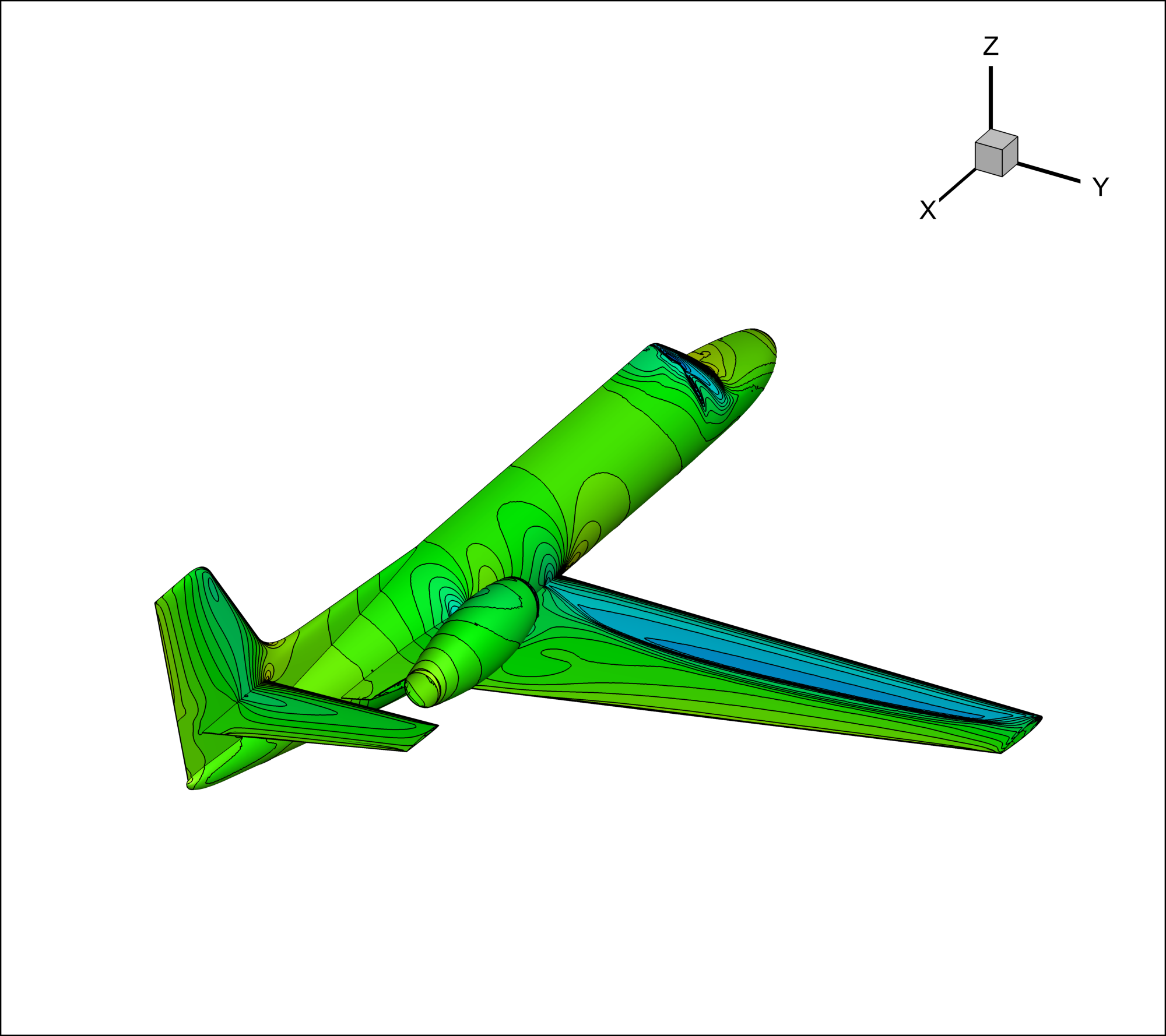
Cp Contours: Mach 0.80, AOA 0
Wing Span [ft] 50.63
Wing Area [sq-ft] 334.2
MAC [in] 77.955
MAC Location
FS267.24, BL151.89, WL1.53
Mach 0.40 Mach 0.80
CLa 0.085 0.105
CD0 223 counts 369 counts
NP 44% MAC 36% MAC
CLmax (flaps up) 1.4
Low Speed Tests:
The aircraft already shows undesirable characteristics at Mach 0.40. Figure 3 shows the streamlines at 0 and 10 degrees angle of attack. Overall, the flow is attached at 0 AOA. The wing-fuselage intersection has significant issues with local flow (e.g. the stagnation point at the root is several inches along the upper wing surface); a wing glove is needed. The previously mentioned canopy loft issue appears as a faint blue area in the pressure contour; no separation appeared at Mach 0.40.
At 10 degrees AOA, a separated region appears in the wing root area. Unfortunately, this separation is likely to have a strong negative impact on the jet intake. At higher power settings and higher AOAs, strong separation will likely be entrained by the intake. Again, a careful redesign of the wing root region will be required.
The pylon region connecting the engine nacelle and the aft fuselage also exhibited poor aerodynamic behavior. Figure 4 shows the streamlines and pressure contours on the aft fuselage in the pylon region at Mach 0.40 and 0 AOA. The pylon is situated in a downwash region of the aft wing, resulting in an excessive suction peak on the lower surface. At other conditions, a shock appeared in this area. The pylon must be redesigned.
In general, the low speed aerodynamics of this reverse-engineered Citation model are not satisfactory. A low speed wind-tunnel test of the existing geometry is strongly not advised.
High Speed Tests:
Testing at Mach 0.80 brought out additional aerodynamic issues. At 0 AOA, a strong shock is seen on the wing, upper pylon, upper canopy, and lower horizontal. See Figure 5 for streamlines and pressure contours at Mach 0.80 and 0 AOA. The upper canopy region is particularly bad. The adverse pressure gradient (i.e. shock) associated with the non-tangential surface produces a strong separation region. This local shock and separation will produce excessive noise and vibration on the aircraft.
As expected given the classical airfoil, the neutral point moves forward approximately 8% between Mach 0.40 and Mach 0.80. Given that the Citation 2’s tail volume is relatively small, the pylon and nacelle appear to be significant contributors to the 10% aft shift in the NP when compared to wing-only theory (i.e. quarter chord).
The wing pressure contours indicate that the airfoil cross sections are likely from the classical NACA series. These current airfoils are potentially unsatisfactory for high subsonic transport aircraft. Also, these airfoils appear to contribute to the detrimental degradation in the pitch stability in the Mach 0.70 to Mach 0.90 range.
The current aircraft geometry is neither suited for a low speed nor a high speed wind tunnel test. It is recommended that a CAD redesign be conducted before additional testing or expense.
This test should reinforce to the reader that a casual CAD reverse engineering design of existing aircraft has significant risks. The actual Cessna Citation required multiple aerodynamic design iterations and trips to a wind-tunnel to prevent or mitigate the issues presented in this memo.