Author Archives: co

Mystery Hs-126 Photo

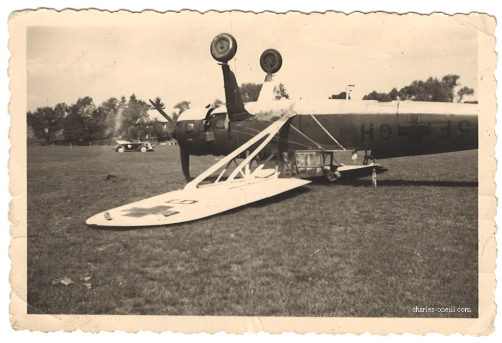
The following Henschel Hs-126 is from our family’s photo archive. This photo was attributed to my grandmother’s brother W.E. “Bud” Hills of the 101st Airborne in WW2. We suspected the photo was taken in France or Germany. There are no annotations.

Henschel 126; Hs 126; WW2

The aircraft is a Henschel Hs 126, an observation aircraft developed in the late 1930s and essentially obsolete and out of production by the early 1940s. The Hs 126 is a surprisingly large platform given the mission. One successor, the amazing Fiesler 156 Storch outperforms the Hs 126 for short, rough, and unprepared flight operations. The other successor, the Fw 189 “Flying Eye” was superior for observation. The aircraft type was rarely used on the Western front after 1940, most were sent to the Eastern Front.

The markings are 5F+GH. Using public sources of German squadrons and locations, we discovered that this aircraft (“G”) was assigned to the 14th Reconnaissance wing (Aufkl. Gr. 14) 1st Staffel (“H”). This would be 1.(H)/14 with known locations in France from 1940 to 1941. The unit was sent to the Eastern front in Feb 1941 and disbanded while back in France in 1942. The Short Range Reconnaissance wing (Naraufkl. Gr. 14) was created in 1943 but was stationed outside of France. Any use of Hs 126 aircraft in 1944 would be unlikely as Me-109Gs were assigned to the unit. Operationally, the Hs 126 was not feasible in 1944.

This leads to the strong possibility that the photo was taken in 1940 during or after the Battle of France. Thus, the photo was brought back by my relative and not taken by my relative. There are other possibilities, but this is the most likely.

Question: What is the make, model and year of the car in the background? Where is the house style/architecture usually seen? Send comments to oneill@aerofluids.com

Power Induced Dihedral

I recently received a question about the effects of propeller thrust on aircraft stability and control (S&C). Within the aircraft design community, we know that power effects to S&C can be a significant engineering effort. Often, the quantification of these effects requires a powered wind tunnel test with a commensurate pricetag. With in the pilot community, we know that power -and especially propwash- significantly impacts (pun intended) the tail’s aerodynamic control power. There are jet aircraft (ex. YC-14, AV-8) using jet exhaust to provide lift and other reactions.

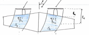
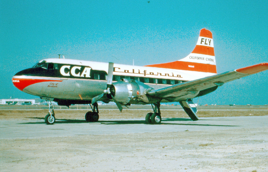
One interesting historical case of a power induced dihedral is the Martin 2-0-2 prototype from the late 1940s. First, let’s discuss the theory. For a twin engine propeller aircraft, the natural design configuration is mounting the engines on nacelles mid-span and in front of the wing.

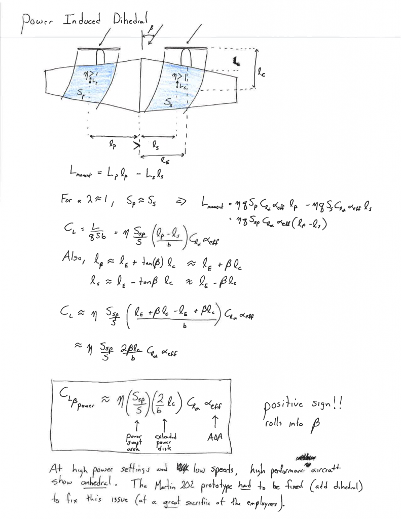
We also know that the propwash has a higher dynamic pressure resulting from the increased flow velocity. The propwash during a sideslip is thus non-symmetric across the wing panels (i.e. more outboard on the downwind panel and more inboard on the upwind panel). The asymmetric flow pattern will induce a roll moment into the sideslip. We call this an anhedral effect (i.e. a positive C_L_beta), which is usually detrimental to the aircraft’s flight dynamics.

In the Martin 2-0-2 design, the prototype encountered S&C problems during flight tests. The solution was to considerably increase dihedral in the outer wing panels. This wing joint would later become a fatigue problem (https://aviation-safety.net/database/record.php?id=19480829-0&lang=en) corrected with the 2-0-2A. Overall the aircraft was not known as a success.

Martin 2-0-2 Production Aircraft
By Bill Larkins – Martin 2-0-2, CC BY-SA 2.0

A derivation of power induced dihedral is shown below. Notice that the magnitude depends on the angle of attack; the effect is worst at low speeds with high power settings.

Feeding your Wolf

There is an old story from an unknown Native American tribe. A wise grandfather tells his grandson that there are two wolves battling inside him. One good and one bad. The grandson asks,

"Grandfather, which wolf wins?". 

The careful reply is,

"The wolf I feed."

Which wolf are you feeding?

This note is written in the time of the Corona virus (2020). You are probably at home. You may even be newly graduated engineering PhD or BS but without a job. Right?

Wrong, you already have a full-time job: You. Your full time job should start to later than 8:00am and end no later than 6:00pm every workday. Give yourself Sunday to rest; you will need it.

Your job search is a priority. Somebody is hiring; you just don’t known them. They don’t know you. You have a unique opportunity to impress. Make a list of engineering skills that you can learn, improve, or teach. Start with these:

  • Learn how to use CATIA. Get a student license for $100. This is an essential communications skill.
  • Start a website detailing your skills and capabilities
  • Teach a short course and post on Youtube. Break into 15 minute segments and use a screen capturing program to show the process.
  • Learn how to use rendering software. This skill allows you to make compelling proposal and project graphics.
  • Volunteer to be a journal reviewer
  • Learn how to simulate electrical systems with LTspice
  • Learn how to simulate structural or fluid systems. Example ANSYS.
  • Learn how to use Simulink in Matlab
  • Join an association outside of your area of expertise. Do a deep-dive into the association’s library of materials. Take notes.
  • Get your Part 107 unmanned pilots license. Get your Technician or General class amateur radio license. Find other certifications that you can complete.
  • Update your python programming skills. Make a GUI multi-threaded frontend for a task that you use often. Post on website.
  • Practice writing.
  • Take an AI/ML course: OCW or youtube or a book.
  • Read through all of the SBIR projects offered by NASA, DoD, DOE, etc. How do your skills match? Find and document a project that you could feasibly complete. Search through old SBIR funded announcements and see which company won similar projects. Send your project capabilities to this company. Voila; instant job opening.
  • Get a post-doc position.

Make a deadline. Complete on-time. Show deliverables.

Why does this work?

Pareto’s 80/20 rule: https://en.wikipedia.org/wiki/Pareto_principle

  • 80% of your colleagues won’t search for ways to improve.
  • Of those remaining, 80% won’t finish & document even one task.
  • The 4% (i.e. 20% ∙ 20%) are exactly what your future boss is searching for in a new employee. You demonstrate competency and are low-risk.

I believe that you should update your resume with a “Quarantine” work history showing what you accomplished. The key point for your future boss is demonstrating a strong work ethic at-home with no supervision. This requires documentation and links to delivered product/projects.

Now, go feed your wolf.

Continue reading

Flight Test Engineering Course (UA)

In the Fall of 2019, I developed and taught a course in Flight Test Engineering to a select group of undergraduates in Aerospace Engineering and Physics.

Topics were divided into 1) performance, 2) stability & control, and 3) logistics, operations & hardware.

  • Performance
    • Atmosphere
    • Airspeed
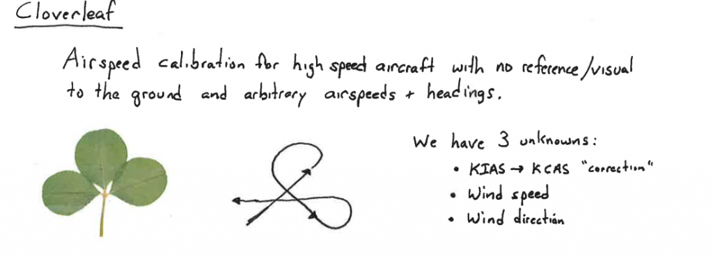
    • Airspeed & Static Port calibration
    • Takeoff
    • Stall
    • Climb Theory
    • Sawtooth climbs
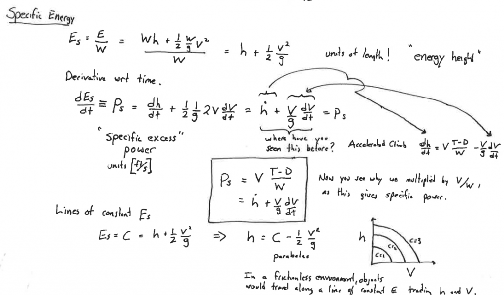
    • Level acceleration & Excess power
    • Level Flight Performance
  • S&C
    • S&C Theory
    • Neutral Point Estimation
    • Stick Forces, Stick force per g
    • Maneuvering Point
    • 6 DOF Aircraft Dynamics
      • Phugoid
      • Short period
      • Spiral
      • Roll substidence
      • Dutch roll
    • Flying & Handling Qualities
    • Inertial Coupling
  • Logistics, operations, & hardware
    • Data reduction
    • Flight test instrumentation
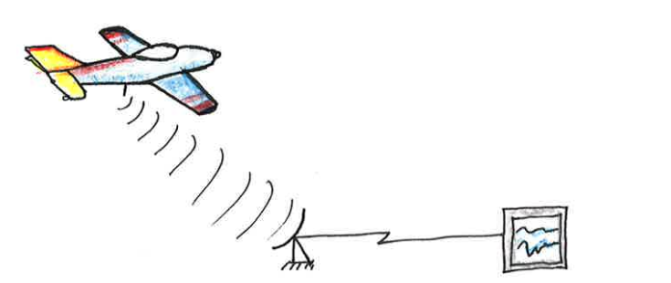
    • Telemetry
    • System identification

Lecture note samples:

The students were required to learn the theory, maneuvers, and analysis necessary to conduct flight testing. We used experimental data collected by the instructor (me) and the students.

Textbook: I assigned Kimberlin’s Flight Testing of Fixed Wing Aircraft; however, Ward’s Introduction to Flight Test Engineering was a primary resource.

Wing Vortex Question

Q: Could you explain to me why the vortex does not appear to be coming from the tip of the wing, but rather several feet closer to the fuselage on this Boeing 777?

Boeing 777 vortex – Unknown photographer

A: Good question. The answer is that the vortex is visible where the change in lift distribution -and thus, shed vorticity- is highest. The flaps are extended, which creates a sharp discontinuity in the wing geometry and lift distribution.

Here’s the physics:

  1. The extended flaps increase both the wing area and the effective angle of attack for the inboard wing. (see: Thin airfoil theory)
  2. The increased area and angle of attack increase the lift being generated on the inboard panel.
  3. Shed vorticity is proportional to the spanwise derivative of the lift distribution.
  4. The vortex rotation decreases the local air pressure and temperature below the dew point. Water vapor condenses into a fine mist. We see this fine mist.
  5. The vorticity is transported downstream (i.e. Helmholtz rule #3)

More information:

  • Notice the spanwise lift coefficient is visually displayed with a vapor cloud above the upper wing. This cloud confirms that the spanwise lift coefficient has the largest decrease at the flap tips.
  • You should remember that the entire wing is shedding vorticity. We see the vortex at the flap tip. If the humidity were higher, we might see additional vorticies.
  • Ground effect is responsible for the slight outboard track of the visible vortex. As the aircraft descends further, the shed vortex will likely be pushed further outboard; induced drag (for a given CL) will decrease.
  • It is not true that a vortex is only generated at wingtips or flap tips. Physics demands a smooth lift distribution (regardless of what we see).

A Summer in Greenland (Part 1: Getting there)

In 2019, I spent the summer in Greenland at EastGRIP on the permanent ice sheet. This is a overview of the deployment. The Remote Sensing Center where I worked received funding from the University of Copenhagen’s Niels Bohr Institute (NBI) and NSF to develop ice and snow radars. Our objective was to perform fine resolution ice layer measurements with radar systems mounted on a surface vehicle. At the end of the summer, our project deliverables were: 4 systems built and operated including the first known ice-layer survey in the L-band (1-2 GHz). This was a unique and enjoyable opportunity.

Continue reading

The Mystery Proceedings

At the end of 8th grade, I anonymously received the 1989 Proceedings of the National Space Society’s Eighth Annual International Space Development Conference.

To this day, I have no idea who sent it.

Someone knew of my interest in aerospace. I have no idea why they picked these particular proceedings, as it was well past 1989. I still have the book. Thanks to anonymous! Sometimes the mysteries of life are never known.

Aircraft Dutch Roll with No Dihedral?

Months ago, an excellent question appeared on the Modeling Sciences sub-forum of rcgroups.com concerning an flight-dynamics aerospace engineering topic: Is dutch roll possible in an aircraft with zero effective dihedral?

The answer is yes.

Simplified Yaw-only Analysis

The dutch roll flight mode shows up in a yaw only behavior driven in frequency by the yaw stiffness Nβ and in damping by yaw damping Nr. A pilot would identify the behavior as a snake dominated dutch roll behavior. With zero effective dihedral, we could also reasonably expect only little to modest yaw-roll coupling through the rate terms, which would be primarily driven by the vertical offsets of surfaces. For the engineers, this simplified 2DOF model of dutch roll has a frequency and damping term approximated as: (derivation)

Interestingly enough, the dutch roll behavior seems to appear even if the aircraft has zero effective dihedral AND zero effective yaw stiffness, provided the product of yaw damping and sideforce derivatives are positive. Both Nr and Yβ are almost always expected to be negative.

Coupled Roll-Yaw Analysis

The dutch roll flight modes show up in higher fidelity dynamics models. The lateral 4DOF model below contains the spiral, roll, and dutch roll modes with sideslip, roll rate, yaw rate, and roll angle perturbation states:

Continue reading

[Book Review] Failure Is Not An Option by Gene Kranz

Failure Is Not An Option describes the Mission Control career of Gene Kranz, the archetypal spacecraft flight director. The book covers the period from Mercury to Apollo with additional chapters of Gene Kranz’s early life and USAF pilot experience.

This book is a gem in that Kranz tells the story of the people, the machines, and the infrastructure. He clears shows the challenges, the solutions, the trials, the magnificent success of the Apollo program, and how NASA moved on.

I particularly enjoyed the discussions of infrastructure development (e.g. flight computers, tracking networks). Several of his insights were introduced into my own R&D group, as we see similar challenges. This book would be useful for startup managers and those people developing the infrastructure needed for a complex engineering or science program.

Strongly recommended for aerospace engineers and program managers.

“The Kranz Dictum” after Apollo 1

Spaceflight will never tolerate carelessness, incapacity, and neglect. Somewhere, somehow, we screwed up. It could have been in design, build, or test. Whatever it was, we should have caught it. We were too gung ho about the schedule and we locked out all of the problems we saw each day in our work. Every element of the program was in trouble and so were we. The simulators were not working, Mission Control was behind in virtually every area, and the flight and test procedures changed daily. Nothing we did had any shelf life. Not one of us stood up and said, “Dammit, stop!” I don’t know what Thompson’s committee will find as the cause, but I know what I find. We are the cause! We were not ready! We did not do our job. We were rolling the dice, hoping that things would come together by launch day, when in our hearts we knew it would take a miracle. We were pushing the schedule and betting that the Cape would slip before we did.

From this day forward, Flight Control will be known by two words: “Tough” and “Competent”. Tough means we are forever accountable for what we do or what we fail to do. We will never again compromise our responsibilities. Every time we walk into Mission Control we will know what we stand for. Competent means we will never take anything for granted. We will never be found short in our knowledge and in our skills. Mission Control will be perfect. When you leave this meeting today you will go to your office and the first thing you will do there is to write “Tough and Competent” on your blackboards. It will never be erased. Each day when you enter the room these words will remind you of the price paid by Grissom, White, and Chaffee. These words are the price of admission to the ranks of Mission Control.