Solving a Convection PDE

The problem under consideration is a linear convection PDE.

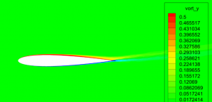
\(\) From Farlow’s “Partial Differential Equations for Scientists and Engineers”, chapter 15 problem 3 is $$u_t = -2u_x \quad -\infty < x < \infty \quad 0<t<\infty $$$$ u(x,0)=e^{-x^2}$$

Intuition

We see that the governing equation is a linear convection problem. The characteristic velocity is 2. We expect the solution to be a shifted initial condition $$u(x,t)=e^{-(x-2t)^{2}}$$

Continue reading

Standard Atmosphere and Airspeed

This post provides a visual characterization of a generic flight envelope with a standard atmosphere. The following figure shows a generic flight envelope map.

KCAS, TCAS, Mach, Dynamic pressure, Temperature

Atmosphere and Airspeed

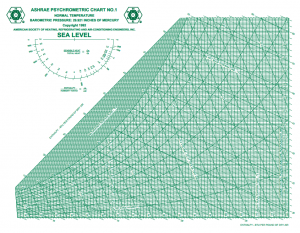
A pdf version is available at airspeed-2014c.pdf. This file plots altitude (0 to 50 thousand feet), calibrated airspeed (0 to 1000 KCAS), true airspeed, Mach number, dynamic pressure, static pressure, and total temperature on one handy page.

Airspeed:

Engineers and pilots track three different speeds:

  1.  Calibrated Airspeed: the airspeed from the pitot system corrected for instrument bias
  2. True Airspeed: actual speed through the air
  3. Groundspeed: speed referenced to level ground

Continue reading

F-35 Economy of Scale

Photo (c) Andy Wolfe

Photo (c) Andy Wolfe

The F-35 Joint Strike Fighter (JSF) was conceived as a 5th generation fighter with a tri-service economy of scale. The late 1990s philosophy is stated as: “The rising unit costs of military aircraft and the new emphasis on greater commonality of aircraft designs among the services tended to push procurement trends toward ever smaller numbers of even more complex and expensive fighters designed to offer multirole and cross-service capabilities. [1]” A post-design analysis by RAND 20 years later estimates that the JSF’s life-cycle cost is 65% higher than a single-service fighter rather than the promised 16% lower life-cycle cost [2]. As of mid-2014, the F-35’s flight envelope is restricted to Mach 0.9, 3 g’s, and 3 hours between engine inspections [3]. Question: what is the subsequent impact to F-16 and A-10 mission replacements if the F-35 program continues having fielding issues?

[1] M. Lorell and H. Levaux, The Cutting Edge: A Half Century of U.S. Fighter Aircraft R&D, RAND, 1998.

[2] M. Lorell, M. Kennedy, R. S. Leonard, K. Munson, S. Abramzon, D. An and R. Guffey, Do Joint Fighter Programs Save Money?, RAND, 2013.

[3] A. Mehta, “Some F-35 Flight Restrictions Lifted,” DefenseNews, 2014. [Online]. Available: http://www.defensenews.com/article/20140729/DEFREG02/307290036/Some-F-35-Flight-Restrictions-Lifted.

The amazing Dassault Mirage III

300px-RAAF_Mirage_III_1

Photo by TSGT CURT EDDINGS

The Dassault Mirage operational career spans 50 years in its many variants: mid 1950s until 2014. By modern standards, the aircraft design is exceptionally simple yet particularly capable.

[The Mirage III] was the first French aircraft to incorporate area rule technology and the first to exceed Mach 1.5 in flight. Nevertheless, Dassault employed only 14 engineers and draftsmen in its design and only 70 shop fabricators in its assembly…. The pre-production Mirage III A, which first flew in May 1958 reached a speed of Mach 2.2 and an altitude of 82,000 feet one month later. It differed from the earlier prototype chiefly in having an improved flight control system and somewhat more powerful Atar engine. [1]

The design time to first flight was an astonishing 9 months [1]. Dassault’s design groups operated on an incremental modification and prototype strategy. Designs failing to reach viability or exhibiting increasing risk were terminated cheaply and quickly (i.e. Mirage III G, variable sweep version). The Mirage was sold worldwide for many decades.

[1] R. Perry, A Prototype Strategy for Aircraft Development (RM-5597-1-PR), RAND, 1972.

Work of Art?

What is a work of art? Can engineers create works of art? Or are creative works of art solely seen in performance arts?

This is the question under consideration in this post. Let us review some images.

http://www.bugatti100p.com/

http://www.bugatti100p.com/

"Hughes H-1 Racer Replica Oshkosh 2003" by FlugKerl2 - Own work. Licensed under Creative Commons Attribution-Share Alike 3.0 via Wikimedia Commons - https://commons.wikimedia.org/wiki/File:Hughes_H-1_Racer_Replica_Oshkosh_2003.jpg#mediaviewer/File:Hughes_H-1_Racer_Replica_Oshkosh_2003.jpg

Hughes H-1 Racer

"HughesH1RacerTailTip" by 350z33 (talk) - Own work. Licensed under Creative Commons Attribution-Share Alike 3.0 via Wikimedia Commons - https://commons.wikimedia.org/wiki/File:HughesH1RacerTailTip.JPG#mediaviewer/File:HughesH1RacerTailTip.JPG

Hughes H-1 Racer Tail

"North American F86-01". Licensed under Creative Commons Attribution-Share Alike 3.0 via Wikimedia Commons - https://commons.wikimedia.org/wiki/File:North_American_F86-01.JPG#mediaviewer/File:North_American_F86-01.JPG

F-86

It seems that engineers don’t need to join a performance art troupe to create works of art.

Rapid Analysis of a Reverse-Engineered Aircraft

Full memo: AEM495-2014-M02-revA

This post concerns a reverse engineered CAD model of the Cessna Citation 2. The objective of this memo is to provide a quick evaluation of the model with respect to the aerodynamics.

The model was supplied in a .STEP format by GrabCAD.com. It should be noted that the loft geometry presented is not an official Cessna geometry; the geometry was solely determined by reverse engineering. The as-supplied model required moderate loft-cleanup and surface trimming with CATIA. The cleaned model is illustrated in Figure 1. The forward hatch area was particularly difficult as the original model attempted to represent the hatch gaps with a tangential double fillet.

citation-cad

Figure 1: Citation CAD model (full aircraft)

A significant loft issue in the canopy area was spotted with zebra lighting (see Figure 2) at the intersection of the cylindrical fuselage and the complex canopy surface. From the zebra lighting, this region does not appear to be either tangentially or curvature constrained. This canopy loft issue will appear as a local accelerated flow region with detrimental downstream separation. A comparison with the actual Citation surface reveals that the current CAD model poorly represents reality.

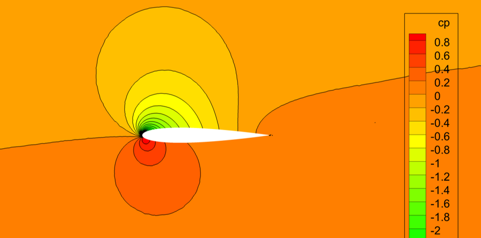
citation-m080a0-iso-contour

Cp Contours: Mach 0.80, AOA 0

Continue reading

Death of a Pilot

Aviation in itself is not inherently dangerous. But to an even greater degree than the sea, it is terribly unforgiving of any carelessness, incapacity or neglect.   

   —Captain A. G. Lamplugh

If you live in the aviation world, death will eventually touch you. The emotional side says “He? Who is next? Me?” The technical side says “Why? How can I learn from this?” Both side can haunt or be buried.

Continue reading

Hoerner’s Fluid Dynamic Drag and Lift

Dr. Sighard Hoerner’s Fluid Dynamic Drag and Fluid Dynamic Lift are classic references in aerospace engineering and fluid dynamics. These books are wonderful for rapid design and analysis work; I adore and treasure my copies. I have received multiple requests for information on purchasing. 

As of 2022, the Hoerner family sells the Drag book at: http://hoernerfluiddynamics.com/. You can also reach them via email at: drag@hoernerfluiddynamics.com

As of 2024, the official source of these books is unknown.

The Lift book is unfortunately not available except on the used-market. But, you should still get it.

Please be aware that the books remain under copyright until 2045. These are worth the price to have your own copies.

The book details are:

Lift ISBN: 978-9998831636

Drag ISBN: 978-9991194448

Hydraulic Jump at Lake Tuscaloosa

Recently, Tuscaloosa received a sustained storm with significant rainfall. The video shows a hydraulic jump (shock) at Lake Tuscaloosa’s spillway (channel flow).

The depth ratio is relatively small. We can compute the Froude number (and the velocity) based on this ratio of depth before and after the jump.
$$\frac{y_2}{y_1} = \frac{-1}{2} + \frac{\sqrt{1+8 Fr_1^2}}{2}$$
For a 10 foot depth before the jump and a 11 foot depth after (generous), the Froude number \(Fr = \frac{v_1}{\sqrt{g y_1}} \) is approximately 1.1. This gives a pre-jump velocity of 20 ft/s. Reasonable based on my video.

L Squared Error for a Fourier Sine Series

How close is my Fourier Sine series to a function f(x)?

Answer: \( L_2(N) = -\frac{1}{2} a_n^2 + \int_\Omega f^2(x) dx \)

This question came up recently while discussing PDE (partial differential equations) solution techniques. The final result is quite interesting.

Our sine series approximates the function f(x) over the domain \(\Omega\) as $$f(x) \approx \sum {{a_n}\sin (n \pi x)}$$ You can determine the coefficients with the formula. $$ a_n = 2\int_\Omega f(x) \sin(n \pi x) dx$$
One good measure of the error between the sine series and the function is the \(L_2\), pronounced “el squared”, error. $$ L_2 =\int_{\Omega} \left( u(x) – f(x) \right)^2 dx $$
Substitute for the sine series to obtain. $$ L_2 = \int_{\Omega} \left({{a_n}sin (n \pi x)}- f(x) \right)^2 dx $$
Expand the terms to obtain $$ L_2 = \int_{\Omega} a_n^2 \sin^2(n \pi x) dx  -2\int_{\Omega} a_n f(x) \sin(n \pi x) dx + \int_{\Omega} f^2(x) dx $$

Now, these integrals are particularly interesting. The first integral is a constant \(0.5 a_n^2\). The second contains the definition of \(a_n\). The third only contains the function \(f^2(x)\). This simplifies to $$L_2(N) = -\frac{1}{2} a_n^2 +\int_\Omega f^2(x) dx$$

Interestingly, if we let the error become zero, the following is an identity $$ a_n^2 = 2 \int_\Omega f^2(x) dx$$ Knowledge of this identity will allow you to quickly compute integrals of squared trig functions.

Neat! Do you have any interesting Fourier results? Let me know in the comments.