The purpose of this page is to develop and distribute a simplified airspeed indicator calibration technique and computer program tool. Calibration from indicated (KIAS) to calibrated (KCAS) is required for certified and experimental aircraft (c.f FAR 23.1323 and FAR 25.1323). There are many techniques and flight test approaches available; however, the mathematics of generating a calibration chart or card can be daunting. This page provides a FREE self-contained airspeed calibration tool for Windows computers useful for subsonic aircraft with minimal calculation and with minimal equipment.
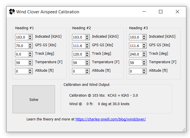
Requirements: You need an indicated airspeed, a GPS with track and groundspeed readouts, a thermometer, and your altitude. You will need to fly three independent headings (approximately 120 degrees apart) for each data point. You will need to download and enter your data into the windclover program.
Non-requirements: You do NOT need any ground references. You do NOT need to know your precise heading or magnetic variation. You do NOT need accurate timing or any clock. You do NOT need to calculate your true airspeed. You do NOT need an aerospace engineering background or on-board flight test engineers or hardware.
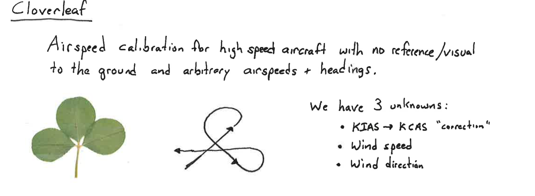
Cloverleaf Flight Profile: You will need to fly three lines that are approximately 120 degrees apart (e.g. 100, 220, 320). Maintain a constant heading, altitude, and indicated airspeed. Using your GPS, record your ground speed and track. Enter these data values into heading columns #1, #2, and #3. The program determines the wind direction/speed and the calibration from KIAS to KCAS.