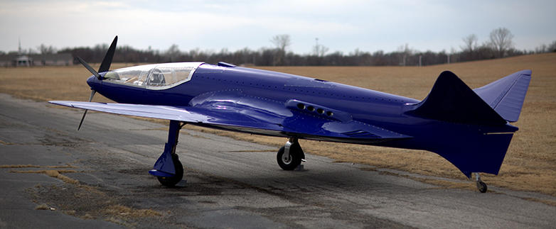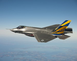
Photo (c) Andy Wolfe
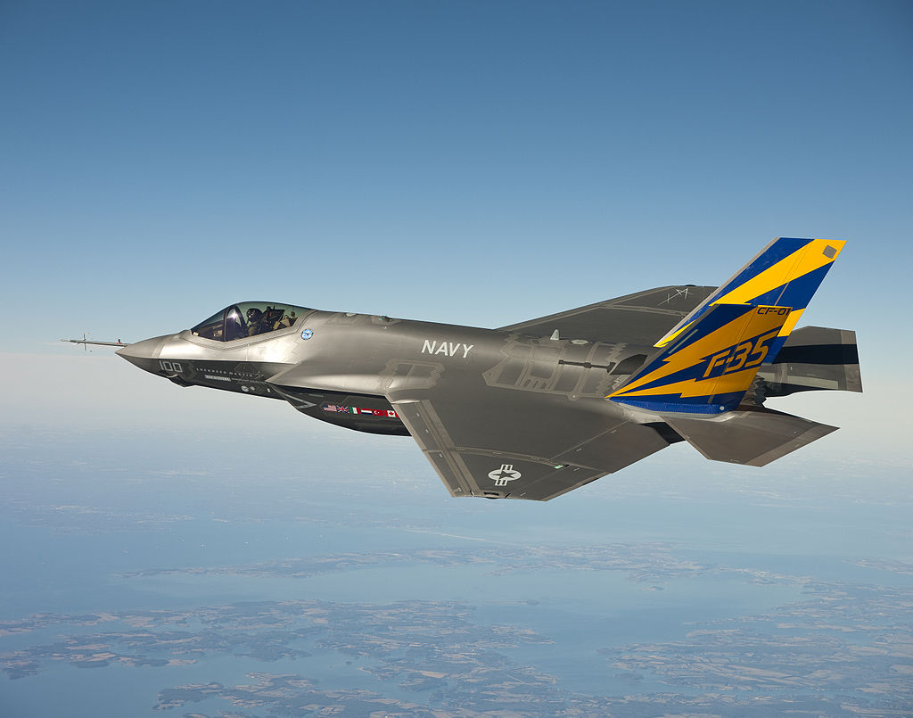
The F-35 Joint Strike Fighter (JSF) was conceived as a 5th generation fighter with a tri-service economy of scale. The late 1990s philosophy is stated as: “The rising unit costs of military aircraft and the new emphasis on greater commonality of aircraft designs among the services tended to push procurement trends toward ever smaller numbers of even more complex and expensive fighters designed to offer multirole and cross-service capabilities. [1]” A post-design analysis by RAND 20 years later estimates that the JSF’s life-cycle cost is 65% higher than a single-service fighter rather than the promised 16% lower life-cycle cost [2]. As of mid-2014, the F-35’s flight envelope is restricted to Mach 0.9, 3 g’s, and 3 hours between engine inspections [3]. Question: what is the subsequent impact to F-16 and A-10 mission replacements if the F-35 program continues having fielding issues?
[1] M. Lorell and H. Levaux, The Cutting Edge: A Half Century of U.S. Fighter Aircraft R&D, RAND, 1998.
[2] M. Lorell, M. Kennedy, R. S. Leonard, K. Munson, S. Abramzon, D. An and R. Guffey, Do Joint Fighter Programs Save Money?, RAND, 2013.
[3] A. Mehta, “Some F-35 Flight Restrictions Lifted,” DefenseNews, 2014. [Online]. Available: http://www.defensenews.com/article/20140729/DEFREG02/307290036/Some-F-35-Flight-Restrictions-Lifted.