“Why does a divergent trailing edge airfoil work? Wouldn’t this increase drag?” A colleague recently asked this question. Good question!
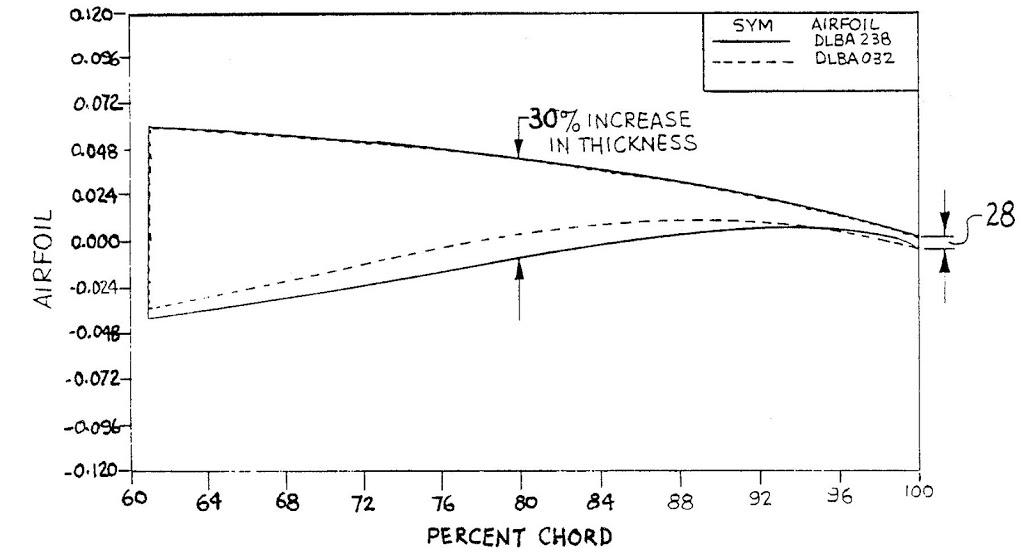 |
| Divergent Trailing Edge Airfoil (Image from Patent US4858852 Fig.2) |
First, we need understand the philosophy of use (application) for this type of airfoil: high subsonic and transonic aircraft designed for low drag about a specified lift coefficient: think long-range transport aircraft from the Boeing or Airbus families. Traditionally (since the 1960s), this application was served by supercritical airfoils such as the NASA SC(2) family.
Here’s a quick discussion of three major reasons the concept works.
- The divergent angles allows for an optimized lower-surface trailing-edge cusp to fill out the pressure profile without cusp separation bubbles. Result: lower Cd
- The divergent trailing edge tends to decrease the blunt trailing edge pressure. This decrease tends to promote less upper-surface boundary layer separation. Result: better Cdc, likely less AC shift
- The mid-chord (say 60% to 80% chord) tends to be significantly thicker. This allows for more flexibility in flap geometry. Result: better low speed performance
McDonnell Douglas Aircraft patented this in 1989: Patent US4858852