Low Reynolds number flows concern flows with a small ratio of inertial to viscous forces. Laminar flow dominates this flow region. Low Reynolds number flight is the most common (birds, insects…) yet it proves difficult and inefficient in human controlled flight. This paper discusses and shows some characteristics of low Reynolds number flows.
The 3 and 4 point Simpson rules numerically integrate equally-spaced discrete data values. The 4 point rule is typically named Simpson’s 3/8 rule. This short note describes an interesting and fast derivation of Simpson’s rules including the associated partial integrals. Non-multiple data point integration is discussed in a surprising finale to Simpson’s 3/8ths rule.
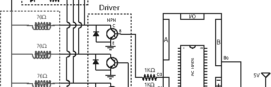
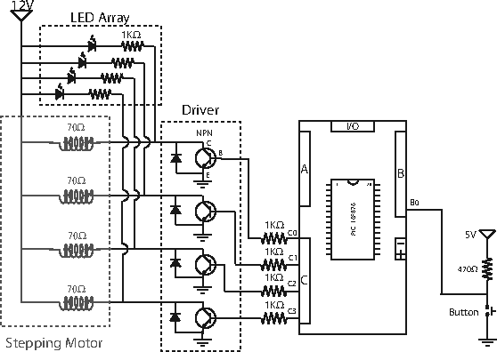
This project’s objective is to describe and control a DC stepping motor. Qualitative stepper motor theory is presented. An example driver with schematic using the PIC16F876 programmed in C is included.
Helicopters can’t fly; they’re just so ugly the earth repels them.
— Anonymous
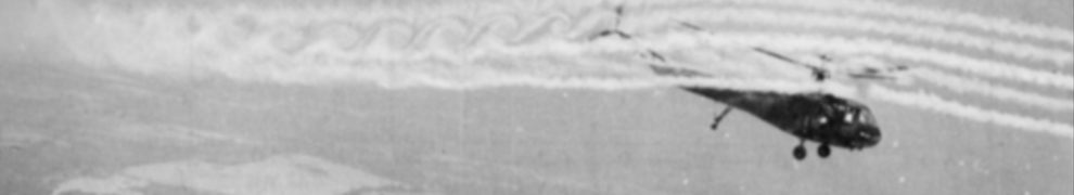
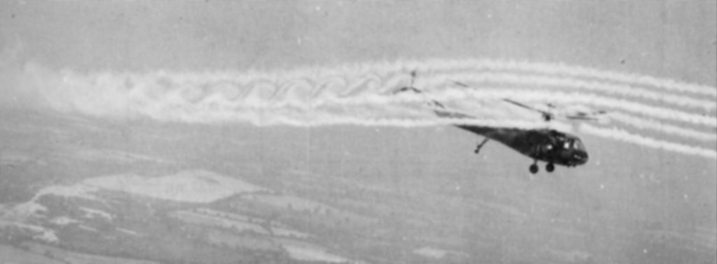
This paper will discuss four areas of unsteady helicopter rotor aerodynamics. First, this paper discusses the classical harmonic solutions to rotational aerodynamics and their relationship to the fundamental Theodorsen solution. Second, modern solution techniques are discussed. Finally, the paper describes wake interactions and their noise production implications.
From: A. R. S. Bramwell, Helicopter Dynamics. New York: John Wiley & Sons, 1976
Unsteady helicopter aerodynamics are complicated. An understanding of the governing physics is possible by isolating simplified systems. Early contributions were based on harmonic analysis. These methods predicted the basic governing fluid physics and warned about blade-wake interactions. Most modern solutions are based on discrete flow representations and computational solutions. These solutions allowed high resolution studies of fluid flow at the expense of physical insight. These discrete flow methods confirmed the blade-wake interaction sensitivities. Blade-wake interactions are shown to create intense and directional disturbances.
The helicopter rotor is a fundamentally unsteady aerodynamic process. Rotor analysis goes from simple 1D shed vorticity models to fully 3D transient turbulent experiments. While the fundamentals of unsteady rotor ?ow are known, an overall theory with a closed form solution is clearly impossible. Further developments in unsteady helicopter aerodynamics will continue as long as the helicopter is a viable transportation vehicle.
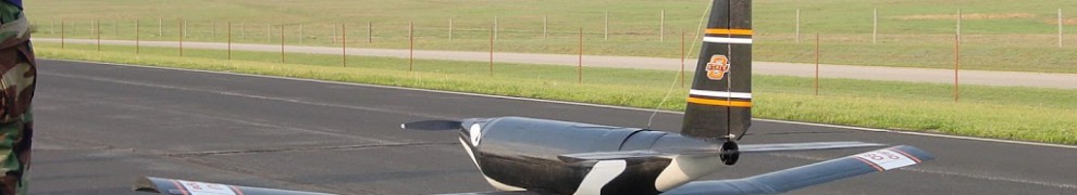
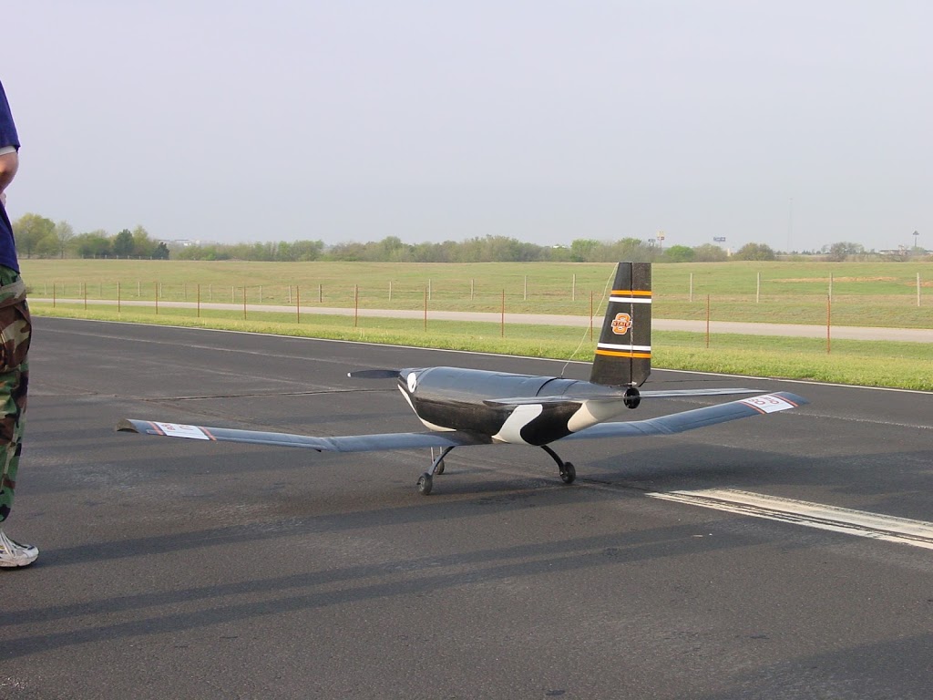
A capstone senior design project completes a formal undergraduate engineering program. Thus, much like the architectural capstone, the engineering capstone course proves, finalizes and protects the underlying structure. My aerospace engineering senior design course at Oklahoma State University followed this tradition by being a semester long, high pressure, team oriented, and successful UAV (Unmanned Aerial Vehicle). Starting from nothing, we designed, built, and flew a competition winning UAV in 4 months.
On runway just before a testflight
Vehicle, Mission, and Competition
The AIAA Design-Build-Fly (DBF) contest provides a yearly international competitive environment for university aerospace engineering students when given a specified mission profile and physical constraints. For 2001, the DBF contest tasked teams with flying two payloads, low density tennis balls and high density steel, around a given flight pattern with a time limit. Score depended on ball volume, steel weight, flight laps, and written project proposal and test-flight reports. The contest was held at NAS Patuxent River, Maryland in April 2001.
Our final vehicle was a low wing, conventional configuration aircraft with a 10 ft wingspan, 1500 Watt motor, and a 16 pound maximum payload. Takeoff at the 35 pound gross weight required 200 ft. The primary structure consisted of carbon fiber skin with a foam core. The untapered, unswept, polyhedral wing consisted of a carbon fiber skin with a foam core; the spar was built-up of both a carbon fiber shear web and a wood spar cap. Configuration details and photos are available at http://bit.ly/Shamu2001. A large horizontal was required for short-field takeoff rotation, so we named the aircraft after a famous killer whale, Shamu. With this aircraft, our team won 1st place among 27 teams. An official AIAA write-up is available at http://bit.ly/Shamu2001-AIAA.
My Role
My role in the Aerodynamics Group was critical for the aircraft’s performance and the team’s success. My primary responsibility consisted of aircraft performance and contest score optimization. I converted the DBF contest’s written “request for proposal” (i.e. rules) into a computational aircraft flight simulation in MathCad for tracking the aircraft’s energy budget throughout the missions. A global optimization routine allowed for optimizing and selecting the plane, motor, and batteries simultaneously. Coordination of detailed performance data and interactions between the Structures and Propulsion groups became increasingly critical as aerodynamics performance, structural weight, and propulsion models developed from conceptual to final design tolerances. As the design process wound down, my responsibilities shifted to construction and then to flight testing. I constructed the wing spars and the carbon-fiber wing skins; the low Re airfoil necessitated smooth skins. Flight test data allowed for performance and simulation tuning, which allowed further score optimization.
Weather uncertainties were amplified by the 200 foot takeoff constraint. Headwind determined the gross weight. This challenge forced a statistical optimization based on the plane and historical weather. Better yet, solving the challenge allowed real-time performance envelope and mission loading data for the flight crew.
During the prototype’s flight tests, the cruise speed was significantly less than predicted. Working with experimental propeller, and motor curves, we identified that the motor winding was customized and differed from the motor’s specification. A correctly wound motor fixed the cruise speed problem.
Airfoil selection was strongly constrained to low Re and high CL. Most airfoils meeting those criteria had strong maximum surface curvature with delicate trailing edges. After browsing experimental wind tunnel data and airfoil profiles, I selected a set of candidates, parameterized their CL, CD, and polar curves, and then simulated the competition score. The Eppler 423 was selected.
I enjoyed my senior design project and the challenges it presented.
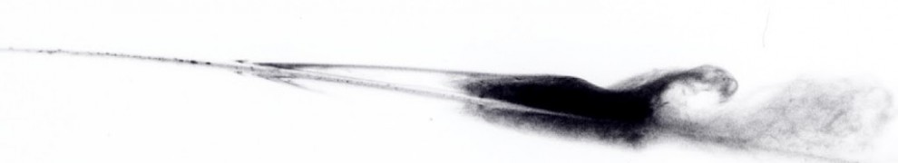
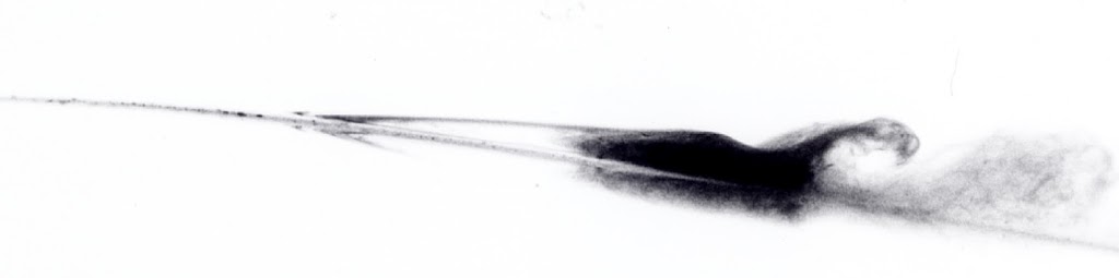
A compressible flow supersonic nozzle using Nitrogen is experimentally tested. A shadowgraph visualization system is setup. Specific impulse calculations are performed from theoretical and experimental data. Compressible flow equations are reviewed.
Includes shadowgraph photos of Prandtl-Meyer fans aft of a nozzle.
Supersonic Nozzle Operating Above Design Pressure (250psi) with P-M waves
The document is available here. This was an undergraduate laboratory experiment.
This design project simulates and controls a beam and ball system. A ball rolls on a pivoting beam. The beam is connected through DC motor through a linkage arm. The objective is to create an output feedback control system. The project simulates the system using Matlab and Simulink.
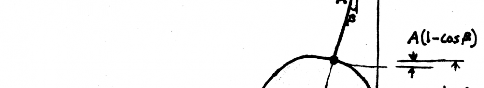
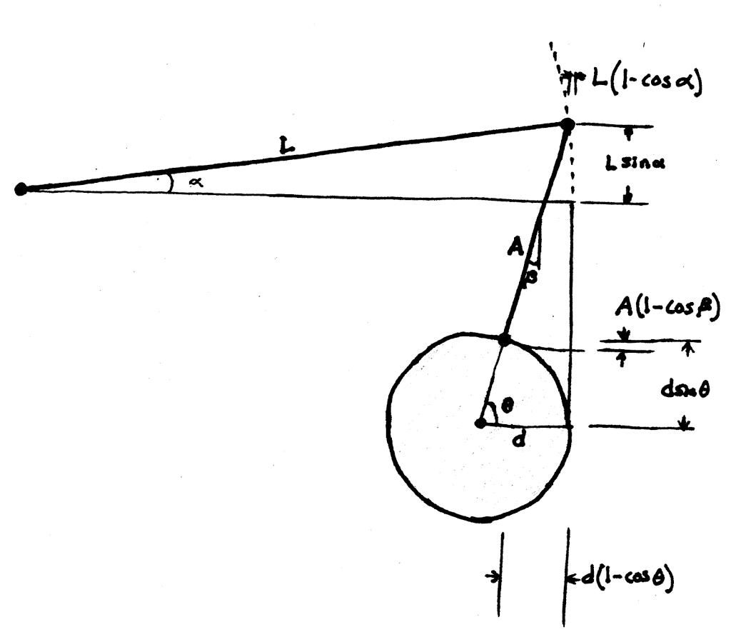
Ball and beam geometry
The physical system consists of coupled linkages and a free-to-roll ball. The linkage motion is nonlinearly coupled to the gear angle. The beam has a length of 1 meter. The gear arm has a radius of 0.03 meters, and the linking arm has a length of 0.2 meters. The ball is steel with a radius of 15 millimeters. The system has 2 energy storage components: beam inertia and ball inertia. System control is allowed through a voltage input into the DC motor, which provides a torque applied at the gear arm. The gear arm motion is harmonic; the gear can go past topdead-center in the straight up and down positions.
Upper Atmosphere and Extra-Planetary Rarefied Flows
MAE 5010 Microflows
Charles R. O’Neill
14 April 2005
This paper’s objective is to survey the Earth’s upper atmosphere,including unique meteorological phenomena and rarefied aerodynamics. The upper atmosphere’s fluid and electrical properties couple in interesting and unexpected ways.
The first section surveys the atmosphere. A meteorology section discusses specific upper altitude phenomena. The final section discusses rarefied aerodynamics.
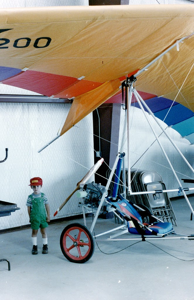
I recently found an old photo from 1983 of me next to a trike. Judging from the background hanger’s appearance, this is apparently the large north hanger at KELK.
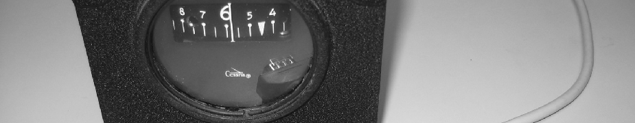
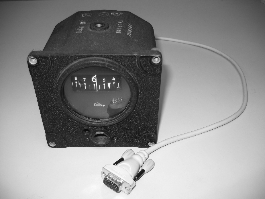
This project developed an one degree-of-freedom electronic aircraft directional gyro (DG). The mechanical inertial gyro in a 1960’s vintage DG was removed and replaced with an stepping motor driven by a micro controller connected to an electronic rate gyro.