Thank you to Adam Benabbou and Sean Sawaya for designing and constructing a new wing for the SPA aircraft. This wing uses the SD7062 airfoil with a balsa and spruce wing structure covered with Monokote. I am looking forward to a series of interesting missions with this aircraft-wing combination.
On 19 March 2018, a tornado hit Jacksonville State University’s campus. The tornado caused widespread damage across the entire campus and the surrounding neighborhoods. The tornado was a direct hit through the quad, library, and almost all major buildings.
The Remote Sensing Center was asked to provide post tornado damage assessment of the campus buildings. We (Tim Leopard, Chris R. Simpson, and I) flew a series of flights over the campus. We wish JSU the best; we hope these helped.
On Windows 10 machines, the default TLS/Schannel cipher is not enabled. When running “DSCheckLS.exe” the license server status will be “NOT RUNNING”.
To fix this, you will need to enable a specific cipher. In an administrator’s powershell, type: Enable-TlsCipherSuite -Name “TLS_DHE_DSS_WITH_AES_128_CBC_SHA”
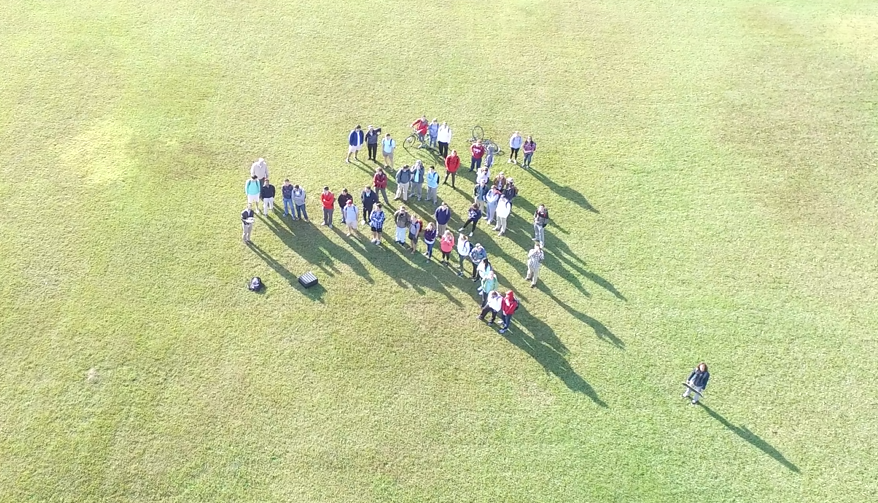
The Civil Engineering CE 260 “Surveying” instructor for the Fall of 2017 asked me to give a guest lecture and flight demonstration of UAVs for civil engineering applications. The class began with a short lecture (CE260-UAV) and then transitioned to Bryce Lawn for a demonstration flight over the University of Alabama’s old chapel building. My laboratory took the photos and created a 3D reconstruction of the building suitable for civil engineering analysis.
We concluded with an aerial class photo.
Thank you to the CE 260 class and the Civil Engineering department, especially Profs. Graettinger and Stogner.
For reference, the full raw flight video is here. The careful viewer should note that this flight was conducted in accordance with FAA regulations and University of Alabama requirements. Please don’t replicate this flight without first talking to UA compliance, UA Grounds, and the Tuscaloosa ATC tower.
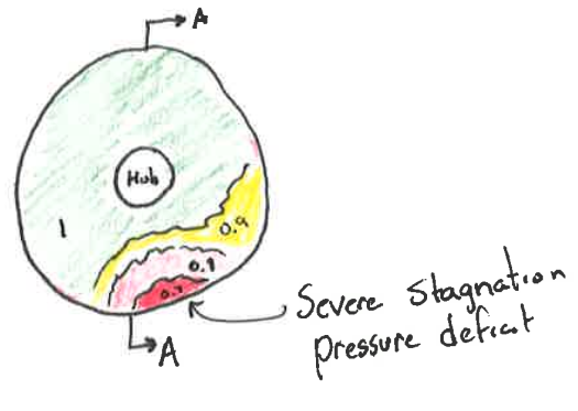
Today, we learn the basics of aircraft inlet design.
This November, I was asked to provide a substitute lecture to a senior level propulsion class (AEM 408). For this lecture, I attempted to provide the basics of inlet design by discussing the relevant physics and constraints.
Inlet fan face total pressure was introduced as a way to quantify the performance of an inlet and to diagnose common issues.
The concept of boundary layer growth with the inlet’s adverse pressure gradient was reinforced from an earlier Aerodynamics I course.
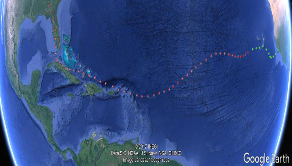
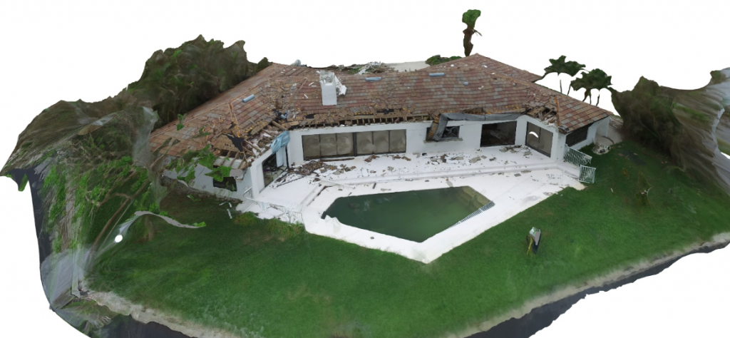
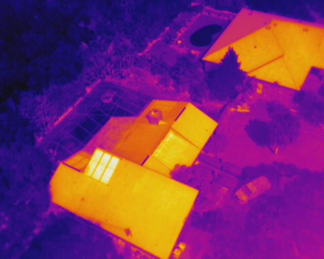
What are the possibilities of investigating storm damage with drones? In 2017, I had the opportunity from a team of Civil Engineers at the University of Alabama to demonstrate a rapid deployment to the gulf coast of Florida after Hurricane Irma.
Hurricane Irma formed off the west coast of Africa on the 27th of August 2017. By the 9th of October, Irma was a category 5 storm off the east coast of Cuba. Irma made landfall at the Florida Keys on the 10th of October at noon as a Category 4. Mainland landfall was on the night of the 10th as a Category 3 to 2.
Logistics
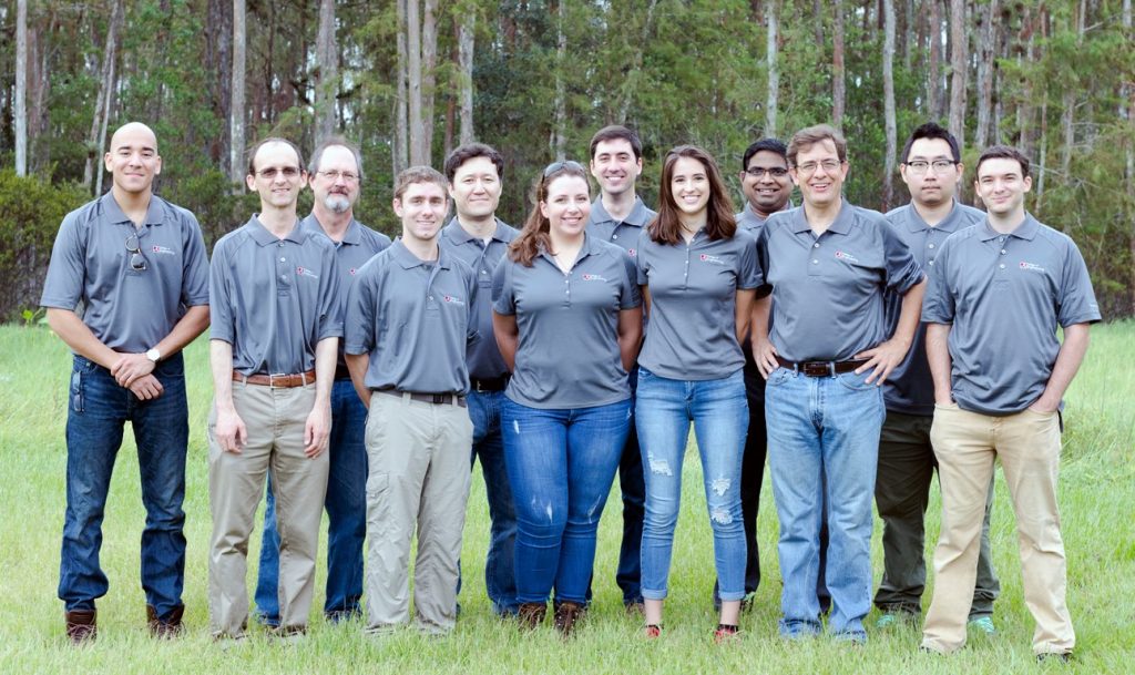
The University of Alabama’s Civil Engineering department rapidly put together a team of approx. 12 members with the specific goal of evaluating the performance of “fortified” homes built to a particular standard. Each of the 4 teams included professors, students, and insurance experts. Teams 1-3 consisted of ground based members surveying the damage, documenting structural and personnel reports, and interviewing inhabitants. Team 4 consisted of UAV operations and a LiDAR scanning crew, with Dr. O’Neill as the professor lead.
The primary lead from the Civil Engineering department was Dr. Andy Graettinger (https://eng.ua.edu/people/andrewg/) with Drs. Kreger, Aaleti, and Hainen.
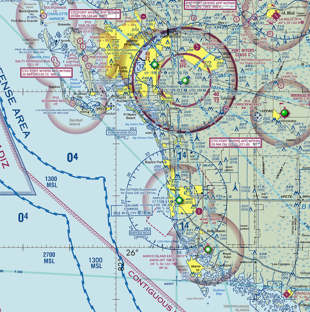
Our equipment was deployed on Wednesday afternoon to be driven to Fort Myers, FL, where the remaining members rendezvoused on Thursday night. We scanned selected locations in Fort Myers south to Marco Island on Friday and scanned the Tampa area on Saturday. The entire crew returned to UA on Sunday and Monday.
The airspace was relatively simple in the Ft Myers area with a mix of uncontrolled, class D, and class C airports. The Tampa area was more complex with class B, and multiple class D airports. I do appreciate the respective ATC facilities for working with us.
Equipment
My aero team brought two UAS platforms with visible and IR cameras.
DJI S900 with an optical camera and IR camera
DJI Inspire with an optical camera
We also brought communications and flight mapping software appropriate for operating small UAS/drones in urban environments.
Operations
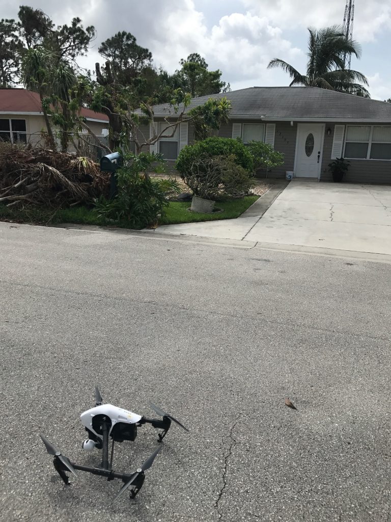
Operating in a post-hurricane environment presented several challenges. The most pressing was take-off/landing access; this includes obstacle avoidance of the passive type (e.g. trees, poles, wires, waste piles, etc) and active type (e.g. people, vehicles, animals, wind-shear/rotor-vortex, etc).
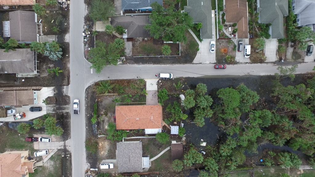
A secondary challenge in low-lying areas was water inundation. Bonita Springs was completely flooded up to 2+ ft.
The worst damage surveyed was along the Marco island area south of Ft Myers.
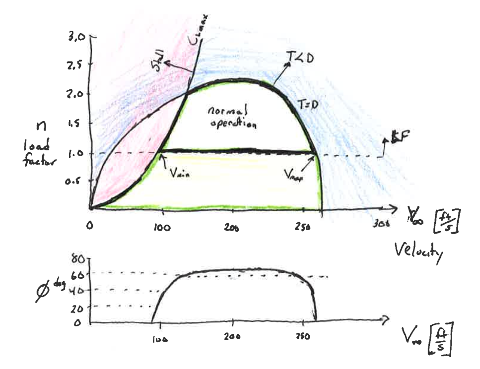
AEM 368 is an introduction to aircraft dynamics including performance and stability and control. Dr. O’Neill taught this course in the Spring of 2017.Example Lectures: